This project is about driving a two speed fan with an Arduino, based on the environment’s temperature.
The project has been designed to help automating an existing fire-based heating system. The idea is that the environment will be warmed faster, by driving heated air into the room with a multi speed fan, while the fire is hot and the surrounding environment not yet.
I wanted to make it a little more interesting by adding a LCD display to show temperature, humidity and fan status, and four buttons to increase and decrease the two temperature values that drive the fan speeds.
When the temperature is below the lowest temperature threshold, the fan will be running at full speed. With temperatures between the lowest and the highest threshold the fan will be running at half speed and with temperatures above the highest threshold the fan will be off.
This project demonstrates the use of an Arduino (or compatible) micro controller with a temperature and humidity sensor to drive outputs, it demonstrates the usage of a LCD display, push buttons and EEPROM memory storage.
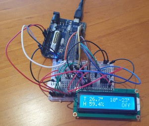
Below I made a short video demo of the resulting prototype.
For the electronic components of the project we need:
- Arduino or similar (eg: Arduino Mini)
- DHT22 temperature sensor
- LCD display
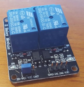
- A two channels relay module
- Four push buttons
- Six resistors – Four 10kΩ as pull-down for the buttons and two resistors for the LCD brightness. In my case the LCD resistors were 1kΩ with 4.7kΩ, with a different LCD and setup I used a 1.5kΩ resistor instead of the 4.7kΩ, it might depend on the LCD manufacturer and on the environment. Alternatively, a potentiometer can be used.
For the software I used four libraries, two of them need to be installed:
For libraries installation please refer to Arduino’s official guide.
EasyButton is helpful to read buttons and complete an automatic de-bounce. It is not strictly necessary as it is possible to read and de-bounce buttons manually, but it requires a bit more coding.
DHTlib helps reading the temperature and humidity values of the DHT22 sensor.
Additionally we use the EEPROM library to store the thresholds into the Arduino’s EEPROM, so that even if the Arduino is powered off, the values can be re-loaded at boot.
Finally we use the LiquidCrystal library to drive the LCD display.
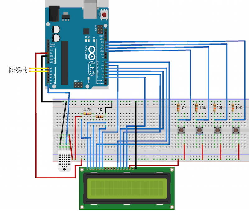
To build (and eventually modify the project) you would need to connect all the components according to the schema and load the code into the Arduino microcontroller.
If no text is visible on your LCD display, you can connect a potentiometer to GND, LCD V0 (3rd pin of LCD) and Vcc, instead of the two fixed resistors of the schema, so that the screen brightness can be adjusted if/when needed.
The code built and used on this project can be found on the GitHub gist below:
I used your project to build a homemade fridge to brew beer, instead of a DHT22 I used a waterproof DS18B20. It worked perfectly
Thank you!
Thank you Mike for your feedback and kind words! It is awesome and rewarding to see that my project was useful to others too, and even better when for completely different purposes!
My son was in a Digital Electronics class in high school this year. He used this as his Year end project and got an A. It is going to be used to cool an overclocked PS4 that gets hot regularly. Thank you for posting!
I am really glad to hear that Jorge! You are welcome!
Hi Enrico, thank you for sharing this nice project. I have replaced DTH with SHT21 and now i have a problem with displaying real time Temp. and Hum. values. When sys started temp. and hum. is displayed and it stays(values) that way all the time…
CODE:
#include
#include
#include
#include
#include
// board led
const int board_led = 13;
// eeprom value
byte eeprom_value;
// timer for sensor and delay
long last_read_from_sensor = 0;
const long sensor_read_delay = 1000;
// maximum and minimum
const int min_value = 0;
const int max_value = 50;
// first value
const int first_value_up_pin = 3;
const int first_value_down_pin = 4;
int first_value = 13;
const int eeprom_address_first_value = 0;
// second value
const int second_value_up_pin = 5;
const int second_value_down_pin = 6;
int second_value = 22;
const int eeprom_address_second_value = 1;
// lcd setup
LiquidCrystal_I2C lcd(0x27,16,2); // Set the LCD I2C address
// outputs
const int first_output_pin = 2;
const int second_output_pin = 15;
// buttons setup
EasyButton button_first_up(first_value_up_pin);
EasyButton button_first_down(first_value_down_pin);
EasyButton button_second_up(second_value_up_pin);
EasyButton button_second_down(second_value_down_pin);
// temperature setup
double current_temperature;
double current_humidity;
// configurable lcd messages setup
const char *message[] = {
“Loading…”, // loading screen
“Max”, // max output speed
“Min”, // min output speed
“Off”, // off message
“T”, // temperature
“H” // humidity
};
void setup()
{
// write boot message on lcd
lcd.init(); //initialize the lcd
lcd.backlight(); //open the backlight
lcd.begin(16, 2);
lcd.setCursor(0, 1);
lcd.print(message[0]);
// turn off board led
pinMode(board_led, OUTPUT);
digitalWrite(board_led, LOW);
// set the two outputs as high
pinMode(first_output_pin, OUTPUT);
digitalWrite(first_output_pin, HIGH);
pinMode(second_output_pin, OUTPUT);
digitalWrite(second_output_pin, HIGH);
// initialise serial
Serial.begin(9600);
// load first value from eeprom
eeprom_value = EEPROM.read(eeprom_address_first_value);
if(eeprom_value != 255)
{
first_value = eeprom_value;
}
// load second value from eeprom
eeprom_value = EEPROM.read(eeprom_address_second_value);
if(eeprom_value != 255)
{
second_value = eeprom_value;
}
// print two temperature intervals on lcd
printIntervals(first_value, second_value);
}
void loop()
{
// read buttons
button_first_up.update();
button_first_down.update();
button_second_up.update();
button_second_down.update();
// increase value if it is high, if it is less than the maximum value, and the first value is less than the second one
if(button_first_up.IsPushed() && first_value < max_value && first_value min_value)
{
// decrease first_value
first_value–;
// write on eeprom
EEPROM.write(eeprom_address_first_value, first_value);
// update two temperature intervals on lcd
printIntervals(first_value, second_value);
}
// increase value if it is high and if it is less than the maximum value
if(button_second_up.IsPushed() == HIGH && second_value min_value && first_value sensor_read_delay)
{
current_temperature = SHT2x.GetTemperature();
current_humidity = SHT2x.GetHumidity();
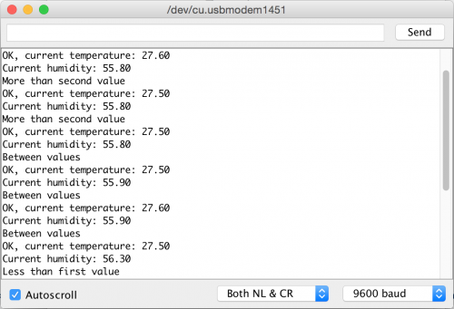
Serial.print(F(“current temperature: “));
Serial.println(current_temperature);
Serial.print(F(“Current humidity: “));
Serial.println(current_humidity);
// print temperature values on lcd
printTemperature(current_temperature, current_humidity);
// turn outputs on/off according to logic
if(current_temperature first_value && current_temperature < second_value)
{
// temperature between two values
Serial.println(F("Between values"));
// print speed on lcd
printStatus(message[2]);
// half speed
digitalWrite(first_output_pin, LOW);
digitalWrite(second_output_pin, HIGH);
}
else
{
// temperature higher/equal second_value
Serial.println(F("More than second value"));
// print speed on lcd
printStatus(message[3]);
// off
digitalWrite(first_output_pin, HIGH);
digitalWrite(second_output_pin, HIGH);
}
}
// set the last read as now…
last_read_from_sensor = millis();
}
void printIntervals(int t1, int t2) {
lcd.setCursor(8, 0);
lcd.print(F(" "));
// add additional spaces if we have less digits than expected on either temperatures
if(t1 < 10) lcd.print(F(" "));
if(t2 -10) lcd.print(F(” “));
lcd.print(temperature, 1);
lcd.print((char)223);
// if only one digit, add final space
if(temperature > -10 && temperature -10 && humidity 0) {
for(int i = 0; i < spaces; i++) {
lcd.print(F(" "));
}
}
lcd.print(status_string);
}
Hi Matic,
Not a problem at all, I am glad you liked it!
Personally I do not have direct experience with SHT sensors. From a quick reading it looks like you need 4 wires and you need to define the sensor variable, passing the data and clock pins.
My suggestion is to get a simple example working with your sensor, verifying the readings by logging them on the Arduino console. Once you get that working, try to apply the changes to my code to get the full project working with a different sensor.
Hope it helps and good luck!